Sunday, 6 November 2011

Rear Uprights #2

Having failed to remove the hubs from the quill shafts with a standard hub - puller, in the end I took the quill shaft back to the engineers and they removed them in minutes using a press. Apparently the proces requires a 50 ton press, and when the hubs do finally separate, they go with a huge bang.  This leaves you with the quill shafts with outer bearings still attached.


The outter bearing is hard up against a shoulder as you can see. Removing the bearing is not easy. In the end I knocked off the brearings leaving this:


Then, with a very sharp cold chisel, I tapped between the bearing and the shoulder to gradually move the race down the shaft. When it was far enough down the shaft, I carefully ground a cut almost through the race. Then I used a cold chisel to open the cut and knock the race off. Nail biting stuff, but it worked for me.


I would like to say that the new bearings go back on easily, and they do, sort of. My first (expensive) effort involved pushing the bearing as far as it would go manually then, opening the jaws of my vice far enough to let the shaft pass through but not the bearing, and tapping the shaft through the bearing. Works great, but when I picked up the shaft, all the bearings fell out.  I had bent the bearing guide out of shape. Don't do this! You will then have to cut the bearing race off again!

Finally, to get the new bearing back on the shaft I pressed them over the splines as far as it would go easily, then used a tube that would just fit over the shaft as a drift and tapped the bearing into place. Easy.

Having got the new bearing on, getting the quill shaft back in and the bearings adjusted is a fiddle, but not difficult.

I first assembled the shaft and bearings without the oil seals or squash tube. Then I tightened up the drive flange on the shaft until the bearings were just loose enough to give free movement.At this point I checked that the hole for the split pin was clear of the castellated nut and I marked the nut and the shaft. Then I greased the bearings, fitted the squash tube the inner oil seal and tightened the drive flange nut till the marks aligned. This needed some pretty heavy hauling on the socket wrench to deform the squash tube, but it worked fine.

Eventually.

I could then fit the front oil seal.


.and the brake back plate:


The hub:


The brake adjuster and the brake slave cylender:


and trial fit the upright


Sunday, 18 September 2011

Rear Suspension

So, onto the rear uprights.

The uprights were not in great shape. One was a poor casting and had suffered quite badly with electrolytic corrosion. So I replaced this one with a spare. However, the spare didn't have the correct length pivot bar, so the rod needed replacing.

Some Vixens use only one shock absorber/spring unit each side at the rear. These use a shorter pivot rod, but the same casting. The Series 1 uses two shock absorbers each side; one either side of the casting, and so needs a longer pivot rod.

The second upright wasn't too bad but the pivot rod had been cut, presumably to get the dampers off, so the pivot rod needed changing on this one too. There was also a seized stud in this one, I got the stud out by welding a nut to the top and turning it out with a spanner. Then I ran a tap through each tread to clean them up and bought 12 new studs to replace the manky old ones,

I managed to get the upper bushes out by cutting off one end, carefully drilling out some of the rubber and then pressing out the tube. After that the bush pushed out easily. Getting the old bearing shells out was not so easy. One of them came out with judicious tapping from behind, but the other three could not be moved, so at this point I took the uprights off to a local engineering shop to get the pivot rods pressed out and new bearing shells pressed in.

So heres what the parts of the pivot bar assembly look like. You can see the pegs with the cut outs to take the rod in the middle of the picture.


clearer view of the pegs


The pegs go in the holes at the bottom of the casting, with the cut out facing up. Its not as clear a picture as I thought, but I think you can see what I mean.


Then the pivot rod is fed through the cut outs


Tightening the nuts grips the rod and holds it firmly.


This is as far as I've got at the moment, because I am having difficulty getting the hubs pulled off  the quill shaft so that I can clean them up. So far I have broken one puller and got nowhere. I did have one sticky moment when I thought the quill shaft spines were worn - the flange clicked slightly when rotated. Happily it turned out to be the splines in the drive flange which is of softer material. I feel another visit to the engineers coming on.

Tuesday, 16 August 2011

Front Suspension Done

OK, not quite. Still no ARB, but I've at least decided what to do about it. I am going to get a new one made up once I have the car on its wheels and can check the measurements properly.


I have fitted the new Avos. Can't decide whether to have the adjuster facing down, where it will probably be exposed to the road dirt but be easy to reach for adjustment, or facing up, where it will be exposed to the road dirt, which will probably sit on it.....Facing down will do for now. It's all coming apart later anyway.


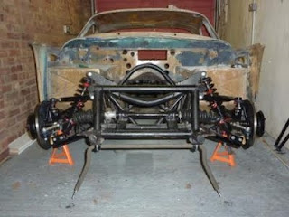
So, here it is with front suspension:


As it turns out I did have to re do the brackets for the brake disc back plates, because they were fractionally out, which distorted the back plates when they were attached and made them rub on the discs.


Here's a gratuitous picture of the nice shiny brake callipers installed:


The more shiny new bits go on, the mankier the chassis looks. Never mind, its going to be powder coated once everything is trial fitted.

I thought I would list all the bits that have gone on the front so far:

New uprights both sides
New stub axles both sides
New trunnions
New top ball joint one side
New bearings
New wheel studs one side
New track rod ends
New polymer bushes
Replacement back plates
New brake discs
Refurbished brake Callipers
New shocks and springs
New near side lower wishbone


Oh God


So, now on to the rear suspension, which, I fear, will have a similar list. I have already dismantled and cleaned the castings and stripped out the old bearings, which bizarrely had sand in on one side! They have clearly been replaced before, because the races are chipped where the new ones have been persuaded into the casting with an engineer's mark one adjuster.

One of the castings did look a bit past it, due to corrosion, in the cold light of day, so I managed to persuade Adrian Venn to part with a second hand spare, in much better condition. I am now considering what to do next, and I am erring on the side of giving them to someone who knows what they are doing, before I brake something. More later.


Monday, 18 July 2011

Christmas comes early

Just a quick post.

I may have mentioned I am a bit of a kid.

In that vein.......


Look what I got!!!!


A complete set of Avo shocks and spirngs care of Adrian Venn at Exactly TVR and my refurbed Girling 16P calipers arrived back from Bigg Red on the same day

Woo hoo!


Ehem........ As you were...........

Friday, 24 June 2011

Finally, the front hubs.

I have been looking forward to getting the hubs on the car for weeks. Its another stage in the rebuild where you can look at the car and see real progress. At the monment I have the front wishbones on and the vertical links in place, but no hubs. Before the hubs go on, I have to clean up and paint the brake disc dust sheilds and this turned into a job of several weekends.

The dust shields that came with my box of bits were not in great shape. They were very rusty but looked like they might be "kind of servicable" once they had been cleaned up, so I treated them to a good soak in Deox - C. They cleaned up OK but even the better of the two looked a bit second hand, even when painted up. The worst one looked more like a doiley than a dust sheild once the "structural" rust was all gone. So, after a week spent cleaning them up and painting them, I admitted defeat and bought a couple of replacements. 

The dust shields on my Vixen are in fact modified TR6 items (surprise!).


On the left, the better of my two original back plates, on the right a TR6 plate.

In the TR6 the small tab holds the back plate to the brake caliper mounting bracket, but in the Vixen, the the tab is not used. A "new" bracket is positioned to locate under the nut holding the track rod end to the steering arm.

It appears that the factory ordered in the TR6 back plates, then drilled off the small tab (you can still see the remains of the spot welds), flattened it out, bent it and then brazed it back on to form a new tab. I had a go at mimicking the Blackpool approach, but the tabs ended up rather mangled, so I made up new ones and welded them on instead.


I've made them a little over-sized just in case. Lack of confidence in my measuring abilities!! I can cut them down to fit later if I need to.

So, now, I was finally ready to get the front hubs back on my Vixen. In the earlier posts you can see that I replaced one stub axle and one vertical link, but, I was never really happy with the condition of the second stub axle. It had been rusty and even once it was cleaned up, the machined surfaces were not great; so I decided to swap out the second stub axle too.

Then I started thinking about the second, original, vertical link. It maybe a little paranoid, but despite the fact that the trunion threads were in good condition, the link was probably 40 odd years old. This shouldn't really be an issue, but I had read somewhere that the vertical links are working at the limits of their design spec. in the Vixen. This niggled me, so, to be on the safe side, I decided to replace that as well. So I threw caution to the wind and ordered a new stub axle and new vertical link - being careful to order the correct side. Vixens use herald drum brake vertical links, but the sides are swaped, right link goes on the left side on the Vixen. So far, so good.

The vertical link came up beautifully having been painted, but heres where it started to go down hill. I had a set of new wheel bearings, and, having cleaned the surfaces,  I fitted the new bearings into the hubs. Standing back to admire my handywork, I noticed that the race on one rear bearing had been ground badly off centre. So they had to come out again and go back. Without bearings the installation was put on hold for a week.

When the new ones turned up, they went in nicely and seemed fine. I was ready to slide the whole assembly over the sub axle, but damn me if now the hub won't go over the (brand new) stub axle. Its not just a tight fit, it wont go on no matter what. On closer examination it turns out the new stub axle has been incorrectly machined and the rear bearing is jamming up.

So, now lacking all faith in the quality of new parts, I ordered two used stub axles, thinking that, since these have already been fitted to a car, they ought to.... well.....fit.

So I rush off to the shed to trial fit the hubs...

Yep you guessed it, they don't fit.

So now I have 4 replacement stub axles of which 2 are too wide at the rear bearing, so the hubs wont push on, and two are too narrow so the axles push straight through withought touching the rear bearing at all. So, following a long phone call with the supplier, we finally alighted on two new axles that were in spec. and they duely arrived the next day.

So now I have the two hubs attached:


Unfortunately, in getting the hub on, I noticed that the rubber boots on both the (new) track rod ends have completely perished, to the point where they just crumbled when I moved them. So, more stuff to go back to the supplier. Annoying but I am really pleased to see the hubs in place finally.

Its starting to look like my goal of getting a rolling chassis by Christmas could be achievable. In order to finish the front end I now need shocks and springs (the old ones are far too far gone), brake calipers, track rod ends (!) and of course the anti roll bar, that I still haven't managed to source.

I am off to Silverstone this weekend, where I hear there will be classic TVRs racing. I will go and make a nuisence of myself in the paddock and see if anyone has any idea where I can get an ARB from.


Saturday, 28 May 2011

Dismantling the rear uprights

This is a job I have been dreading, because, having read up on it, I know (i) it's all too easy to cause a lot of damage with too much enthusiasm (ii) I know just about everything needs unseizing and half the studs and bolts have already been broken off in the ally casting. So it might turn out to be a bit of a bugger.

I've been looking at these uprights every time I got into the shed, for months. So, today I finally bit the bullet, got out my 1 1/4" socket and stripped down the first upright. Everything has been comprehensively soaked in WD40 so it all pretty much came undone without fuss. It had already been stripped to the backplate, so the brake mechanism was not in place. The catellated nut on the rear flange came off with ease; the quill shaft is supposed to come out fairly easily after this, but it did need a bit of a firm tap. The back plate itself came off pretty easily. It may have been off before because it was held in place by a mix of nuts and studs.

The casting cleaned up relatively well with a wire brush, but you can see where one cotter pin and a couple of the studs are sheared off. Its also sufferd a little from electrolytic corrosion between the backplate and the flange, which had expanded and, quite amazingly, bent the backplate out of shape! There had also been some electrolytic damage between the handbrake bracket and its mounting by the look of it.

The flange looks a little rough, but once the broken off studs have come out, I am going to get the whole casting checked over. The rod also looks bent, but I was planning on replacing that anyway.


This is the second upright. It also looks pretty poor.


The bolts that hold the handbrake bracket have also sheared off on this oneand the rod holdng the shocks wishbones and track adjusting arm has been cut, but as for the other upright, I plan on replacing it anyway. One of the cotter pins also seems to have sheared off.

The brakes were siezed fast onto the drum, so I thought I would first try slackening off the adjuster to allow them to loosen up.  No such luck of course, the adjuster had virtually fossilised after 24 years gently corroding, and it just sheared off.

In order to get some purchase on the drum, I undid the nuts holding the adjuster to the back plate and tapped the adjuster into the drum. Then I removed the clips holding the slave cylender and pushed the slave cylender free. This gave a little free play on the drum but not enough to free it off, so finally I undid the castellated nut, pulled off the flange, replaced the nut to protect the thread and tapped the quill shaft. This finally freed the brake shoes and popped off the drum, but now I need a new castellated nut!.

Here are all the bits:


Broken adjuster bottom right.

The quill shaft was still held in place, but it comes out with a firm tap and here it is complete with the front bearing, oil seal and crush tube, whcih you can just about make out on the left side of the shaft, covered in grease.


The bearings will be replaced of course and, obviuosly, the shoes, pins and clips will also need to be replaced. Fortunately, to my great surprise, the slave cylender was fine once it was cleaned up and will need only a recon kit. Unfortunately there appears to be some play between the quill shaft and the flange on this upright so they will probably have to be replaced too. Not sure about the studs; someone has sawn them down .....
Despite the brake pads being siezed onto the drum, the drum itself looks to be in reasonable condition. It just needs an internal clean and visit to the shot blasters to clean up the outside. The other drum will need the same attention.

The casting of this upright looks fine. There is no electrolytic damage between the backplate and the casting, although there are a couple of sheared off studs.

Thanks to the authors of this http://www.zen11896.zen.co.uk/vixen/parts/vixen_rwb.html for the expanation of how to dismantle the hubs.

Friday, 27 May 2011

Odds and Ends

I had always planned to do this restoration systematically, by starting with the front suspension, then rear suspension, get the wheels on to produce a rolling chassis and so on. The problem is that a few small things are holding me up on the front supension at the moment. So I can't resist tinkering with a few of the other bits and pieces that need doing.

The first part I "had a go at" was the steering column. It's from a Spitfire and relatively simple to dismantle and play with. It looked pretty grim when I got it:


But it just needed a clean up and repaint. I tracked down a new light switch on E bay, to replace the old rusty one with no toggle, and now it looks like this:


The next assembly I tackleds was the dashboard, whcih was also in a pretty grim state:


I stripped it of all the metal work and derusted and repained the demister vents. The side air vents were all gummed up, but a soak in warm water sorted them out, and now they even swivel and the covers move! The ash tray was pretty far gone. It cleaned up OK but the lid spring was broken. It took a while to track down a repacement but, by searching Google images I managed to work out that it comes from a pre "Air Flow" Cortina Mk1. I found a good one on E bay and repainted it, so that was all the metal work done.

The bit I was dreading was re-vinyling the dash top. But when it came to it, it was actually quite simple.  Having stripped the dash, I found that the glass fibre panel was cracked and the lip, onto which the dash panel screws, was not in good shape; so I repaired all that with new fibre glass. Then I attached a 10mm foam sheet to the top with contact adhesive and over layed it with new vinyl. The vinyl is available from Woolies Trim. Grained Black 25 was the one I used, and the match is pretty good. The secret is (i) use really strong contact adhesive to hold the edges down; the spray stuff is too wimpy to keep the vinyl attached while you stretch it over the dash top. (ii) warm the vinyl with a hair dryer and it will stretch and conform to the fibre glass panel with no problem. In order to clamp the front of the vinyl, while it dried, I screwed the dash panel to it.


I am really pleased with the result.

On the subject of the dash panel, I have a collection of switches that look like they have been stored on the beach for a couple of years!


 After a clean with a spray contact cleaner, and a little WD40, the toggles at least move. I am in the process of tracking down new switches, but I may have to rely on renovating the old ones. If any one knows another car that has this type of switch, I'd really like to know about it.


Sunday, 8 May 2011

A Little More Progress

Progress has been slow in the last couple of months.

I have made no further progress on the question of the anti-roll bar, so I pressed on with the front suspension. The hubs are rather grubby and have odd sized studs. One looks suitable for steel wheels, the other is the right size for wire wheel splines. No idea why.


Miraculously the brake discs came off relatively easily after an overnight soak in WD-40


At this point I had to decide whether to go for wires or not. I must admit, I do rather like the look of the period "Minilite" wheels, but these cars do look good with wires.

Amongst the oily and rusty bits I found  a set of 4 wire wheel splines. These look like they were bought new at an early stage of the car's restoration, but subsequently allowed to deteriorate, so they were covered in surface rust. Likewise, a set of  new nuts to attach them to the hubs was found in its original bag, but again, all covered in fine surface rust. The car also came with a set of shabby looking, painted wire wheels. The splines don't look badly worn, but no doubt we will see later! Since I don't have anything else in the way of wheels, this is the way I intend to go. So, I ordered a set of correct wire wheel studs.

I finally got the grotty hubs off to a local blasting company.


The result was not as good as I had hoped; the pits still held a lot of rust:


But they cleaned up well will Deox-C paste and I managed, finally, to get them painted.

Pressing out the studs went much smoother than I was expecting. I pressed them out using a vice and a 3/4" socket. I pressed the new ones in the same way and I now have two sets of identically sized studs. I then painted up the hubs with two coats of POR-15 and they are ready to accept the new bearings. Then  they'll be ready  to go back on the car. Before I do that though, I have to sort out the brake back plates, which are quite badly rusted. More on that later.

Thursday, 17 February 2011

More on Anti Roll Bars

So, I believe I said the Vixen ARB was a pretty simple bit of kit...........................I might even have mentioned that the parts list said it used Triumph Spitfire bits.

*Cough*

Well. I got the 22mm Spitfire ARB, and I got the associated mounting kit and I got the polybushes - eventually. Then, before I took the ARB to be powder coated, I realised I had bought the wrong drop links, my fault entirely, didn't read the parts list properly. So in a sudden rush of blood to the head After lengthy consideration, I decided to get some nice rose jointed drop links that were specially made for the car. Here they are


Lovely aren't they?

So, being little more than a big kid really, I immediately set about attempting to trial fit the ARB.The holes in the ARB mounting plate to take the "U" bolt from the mounting kit were too close together by about 3mm, but what the hell? I am a seasoned TVR restorer now, so, rather than worry about this for too long  I gave the "U" bolt a delicate tap with a hammer and it dropped into place perfectly. I was on a roll.


Except that the Spitfire ARB doesn't appear to fit the TVR Series 1 Vixen.


So its back to the drawing board

April 2020 UPDATE:

I had not thought about this issue for a long time until one evening bored in virus lock-down, i was browsing through some old photos I had downloaded from the net, of a Griffith 400 being stripped for restoration and I happened to notice what looked like a spacer between the drop link and the antiroll bar.

A bit more research and I found a series one Vixen with the same spacer:


So I think that's the answer. It looks like the car may have had a Spitfire/ Herald ARB with a spacer.

Having reassembled the ARB and checked it looks like a one inch (25mm), 3/8 ID spacer would do the job. So, just waiting for that to arrive!

Update: Yep that's the one! 


Sunday, 23 January 2011

On the Subject of Anti Roll Bar Bushes

The car came without an antiroll bar, still, no problem, I know that the Vixen uses Herald/Spitfire antiroll bars. Very simple bits of kit. I managed to get hold of a 22mm Spitfire ARB, then a kit of replacement mounts, U bolts and drop links. The car came with a complete set of Superflex bushes, including one for the ARB.

The Vixen ARB bushes from Superflex look like this:


Note the bulge at the bottom. But the Vixen ARB mounting plate looks like this - flat


Since the Vixen uses a Triumph roll bar, I imagine that Superflex assumed the mounts were the same. The Spitfire mount does have a curve in it that would take the bulge. Anyhow, to cut a long story short, it seems that the Vixen ARB bushes should be cylendrical and I am going to get some from Adrian Venn at Exactly TVR (http://www.exactly-tvr.demon.co.uk/)

A bit of Progress

OK, I sussed out the problem with the wishbone mounts. First, the undersize of the hole was down to good old Iron Oxide.

I finally plucked up courage to drill out the holes in the wishbone brackets to 3/8", only to find that, rather than metal shavings, I just got a load of rusty dust! The chassis was painted (maybe in 2001) with Smooth Hammarite and it seems surface rust has begun to develop underneath. In the insides of the hole, and also on the mounting brackets themselves,  the rust is quite thick. A quick clean with the 3/8 drill bit and all was well.

The problem with the new lower wishbone appears to have been acombination of thick rust on the inside of the bracket and one of the hinge tubes being too wide. The opposite wishbone fitted fine and, comparing the two, I found that the new one was about 1mm too wide. So, out with the file, clean up the rust, lube-up and hey presto.


I am really pleased to have finally got to the point of fitting the wishbones and uprights. This is the point when it starts to look like a real car again. Looks great but still a couple of niggles. (i)  I can't for the life of me find a grease nipple that fits the uprights. Even the ones sold to go with the new up right don't fit. The old one fits fine but is rather gnarled and rusty. (ii) I can't get the cones on the upper ball joints to grab the inside of the eye on the vertical link with enough tenacity to do up the Nyloc without the cone spinning.....still, it was about 9:30 and dark when I gave up. Sort that another day!  

On the subject of the rust: If you look at the chassis, yoiu can see that it has quite a few dinks in the coating where rust is starting to take hold. The plan for the chassis is to use it, as is, to mount all the ancillaries and check them. Once I have a rolling chassis with the drive train fitted, I will trial fit the body and measure up for the planned roll cage. This means that any welding or drilling that needs to be done doesn't have to damage the powder coat on the chassis. Also zinc coating a chassis prior to powder coating apparently makes it harder to weld to.

Sunday, 9 January 2011

Reassembly begins

Over Christmas, everyone was sick. I had about 10 - days holiday all told over the holiday period and had hoped to get some work done on the car. But, what with snow and flu, very little got done at all. I had really hoped to get the suspension wishbones and uprights attached, however, things didn't go smoothly. It was not a straightforward "bolt it back together job".

I got the wishbones back from the powdercoaters and they looked fine,

Lowers


Uppers


Poor photography! But they do look good!

so, I rushed off to the garage like a kid with a new toy to fit the bushes and attach the wishbones to the car. Problem one: having fitted the bushes to the new wishbone, I offered it up to the wishbone mounts and it didn't fit. It appears the wishbone is about 2 mm too narrow for the mounts....

Problem two: the top wishbone fits fine, but the spacer tube of the new bushes has a 3/8 inch I/D to take a 3/8 inch pivot bolt. However, the hole in the wishbone mount to take the bolt has a smaller diameter, so the pivot bolt won't go throught the hole, probably just needs drilling out to the correct diameter. I will need to get to the bottom of this before I start messing about with the wishbone mounts on the new chassis. I don't want to start drilling out holes before I am sure. Its easier to drill out metal than it is to put it back again! In the mean time I have to get something bolted back on the chassis!

 I decided to go for the steering rack. The rack was in good condition mechanically, but the track rod ends were both shot. It took a week to get the rack cleaned and de rusted and to clean up the rack mounts and repaint them. I also checked the gaiters and replaced all the gaiter clamps because the old ones were nasty .......and then re fitted the rack!

I have a few receipts from the previous owner so I can tell you the new chassis was bought in February 2001. So there it is. The very first bit to go back on the chassis since February 2001 is the steering rack on the 9th January 2011, almost 10 years since the new chassis and just over 24 years from when the car was taken off the road!


All I have to do now is get to the bottom of the wishbone issue and I will be well on the way.

As a bonus, I have discovered where the cat, disappears to when we can't find him. While I was fitting the rack, I heard a rustling noise coming from the back of the garage. There, sitting in the in well at the rear of the car, where the petrol tank goes, was Jazzy Jeff the cat. There is a small hole in the back garage wall where he obviously sneaks in sits in the back of the Vixen.